
OPC UA: read, write and observe
Complete OPC UA cycle.
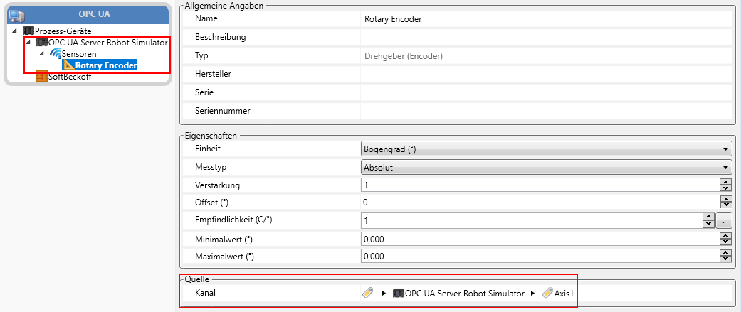
Reference example for OPC UA connectivity: an OPC UA server is started directly from the workflow, then an axis signal is used as a trigger, a velocity value is read, written anew and read again for verification. The example also shows how a sensor can be bound to a process variable and thus measured — for instance to convert a digital input signal into a time signal like a logger does. Finally the server is stopped in a controlled manner.
Workflows in detail
-
SimpleReadWriteObserveTest
Complete OPC UA cycle.
Start → start OPC UA server → trigger axis 1 → read velocity → write velocity → read new velocity → rotary encoder measurement → signal validation analysis → stop server → end; error flow present.
-
Signal Validation
Characteristic block.
Characteristic start → RMS → characteristic end.
Inside the software
Take it with you
Import through the SonicTC DbManager — individually or merged into an existing database.
Ready to experience acoustic test technology in your line?
Send us your part or schedule an online demo. First assessment within 24 hours.