
Complete FRF test cell: modal test, damping & resonance analysis
Complete modal test with an impact hammer at several geometry points.
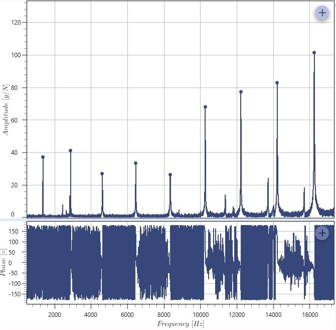
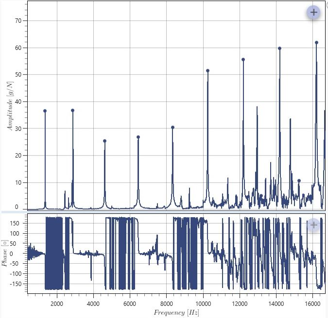
The most extensive configuration bundles several variants of experimental modal and damping analysis in three stations. Force sensor, microphone and acceleration signals are measured under impulse excitation — either with a Maul-Theet impact hammer or an automatic NV-Tech modal hammer (SAM) — while a stepper motor rotates the specimen through several measurement positions; an IVS-500 laser vibrometer complements the sensor set. Damping is determined by several methods in direct comparison (ICF, Ewins, x-dB, RFP), including a coherence evaluation of the first mode. Also included are a purely simulated SISO FRF station and an alarm handling station with SNR/SINAD monitoring.
Workflows in detail
-
Modal Test (Maul-Theet)
Complete modal test with an impact hammer at several geometry points.
Start → initialise → ready/LED on → start trigger → geometry loop (modal loop: impulse → signal trigger force sensor → force/microphone/acceleration measurement → modal analyses MIC and ACC; then motor increment) → motor zero position → end.
-
Modal Test (NV-Tech)
The same test with an automatic modal hammer (SAM) including zero position setup.
Start → initialise → set up zero position → start trigger → geometry loop (hammer trigger SAM → measurements → modal analyses; motor increment) → motor zero position → end.
-
Damping measurement (Maul-Theet)
Three repeat measurements with averaging and decay time.
Start → ready → start trigger → loop "3x repeat measurements" (impulse → measurements → analyses → decay time) → end.
-
Damping analysis FRF
Characteristic block with a multi-method comparison.
Characteristic start → FRF → coherence mode 1 → peak detection → quality factors after ICF, Ewins, x-dB, RFP → characteristic end.
-
Further workflows
Damping measurement with microphone/acceleration sensor, resonance analysis with rotary positioning, motor calibration, a simulated SISO FRF chain and alarm handling with sensor quality monitoring (SNR/SINAD).
Structured like the measurement and characteristic workflows described above.
Inside the software
Take it with you
Import through the SonicTC DbManager — individually or merged into an existing database.
Ready to experience acoustic test technology in your line?
Send us your part or schedule an online demo. First assessment within 24 hours.