
Motor stop profile analysis with ramp & soak PID control
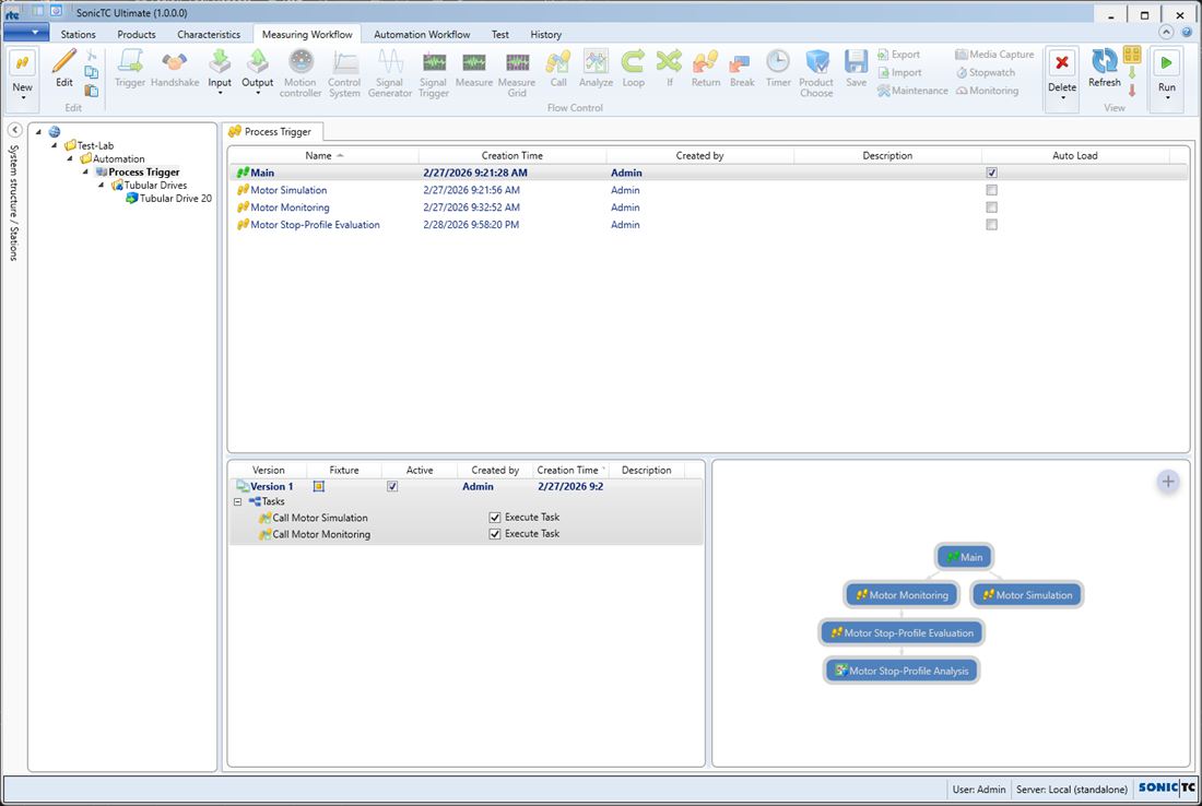
Starts the sub-workflows for simulation and monitoring of both test scenarios.
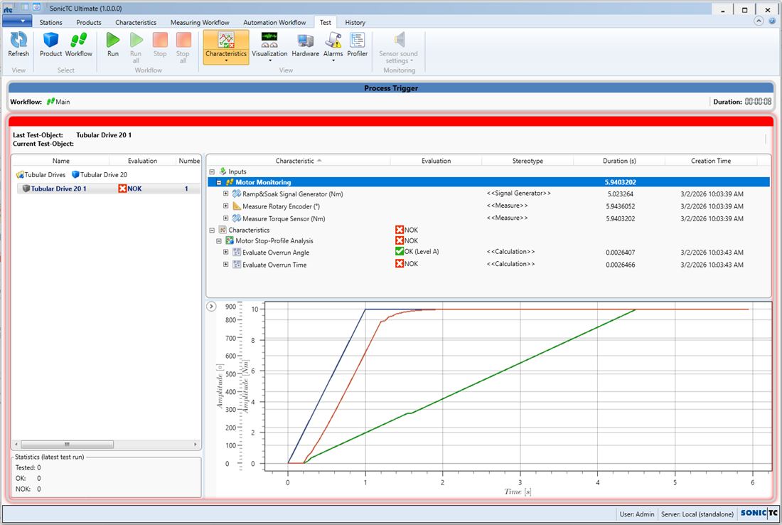
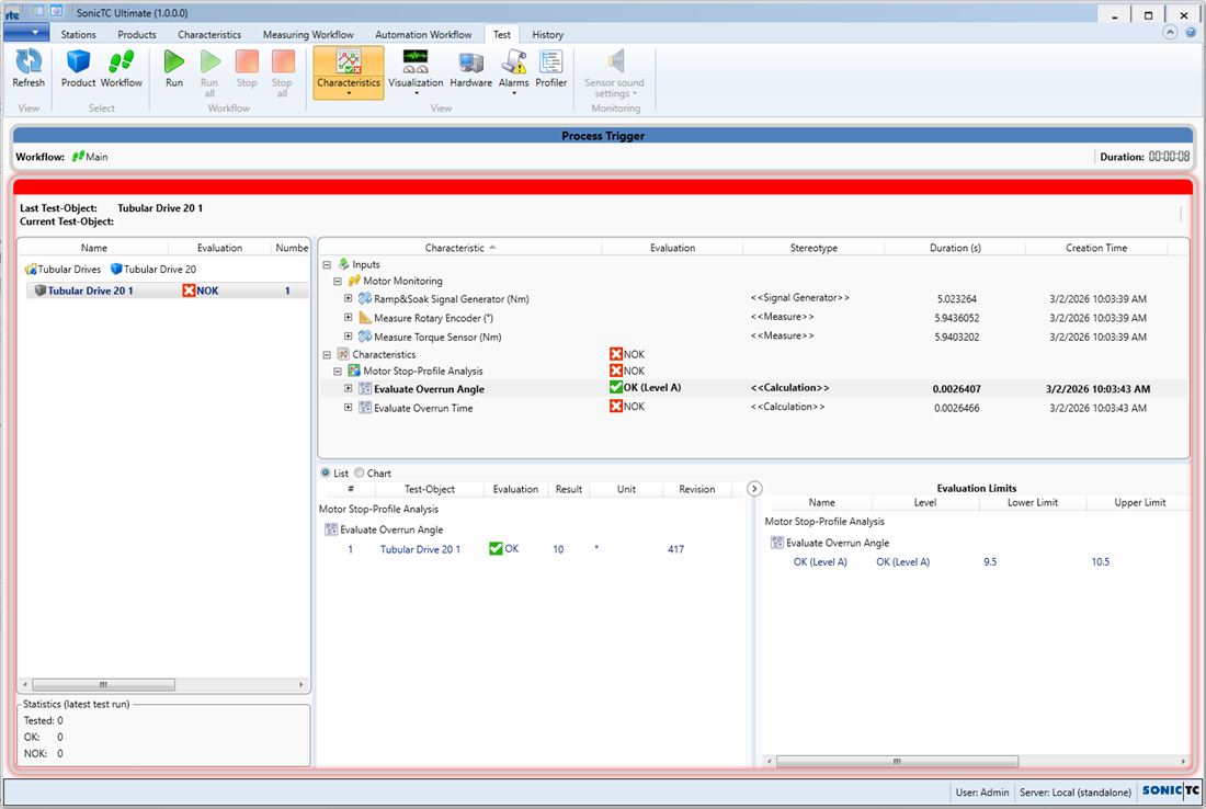
End-of-line test of a tubular drive with two test scenarios: stop profile analysis and limit switch testing. The load torque is simulated through a ramp & soak signal generator with PID follow-up control while torque sensor and rotary encoder are measured. After the motor stops under load, the sequence waits until the angle value no longer changes within a tolerance and evaluates overrun angle and overrun time as characteristics — entirely without an additional measurement task. The limit switch test derives switching states from current measurement signals.
Workflows in detail
-
Main
Starts the sub-workflows for simulation and monitoring of both test scenarios.
Start → call Motor Load Torque Simulation → call Motor Load Torque Monitoring → call Motor Limit Switch Simulation → call Motor Limit Switch Monitoring → end.
-
Motor Load Torque Simulation
Simulates load torque (ramp & soak PID) and motor angle including overrun.
Start → init → torque ramp & soak follow PID → motor angle loop (timer → increment) → angle overrun loop → end.
-
Motor Load Torque Monitoring
Runs the target profile, measures torque and rotary encoder and calls the evaluation.
Start → start motor → ramp & soak signal generator → torque sensor measurement → rotary encoder measurement → call Stop-Profile Evaluation → stop motor → end.
-
Motor Stop-Profile Evaluation
Waits for the motor to stop and captures the last angle through a trigger.
Start → motor running timer → handshake "Wait For Stop" → loop (angle trigger) → set overrun variables → stop profile analysis → end.
-
Limit switch test (4 workflows)
Simulation, monitoring, evaluation and state analysis of the limit switches.
Simulation and monitoring run in parallel; three current triggers on the ammeter set the limit switch states, which are evaluated through a calculation expression.
Inside the software
Take it with you
Import through the SonicTC DbManager — individually or merged into an existing database.
Ready to experience acoustic test technology in your line?
Send us your part or schedule an online demo. First assessment within 24 hours.